Whole-House Assessment in Mystic, CT: Sagging Girders and a Ridge Beam
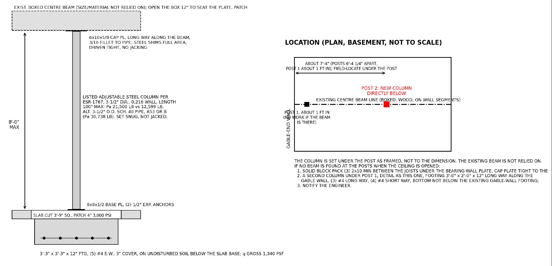
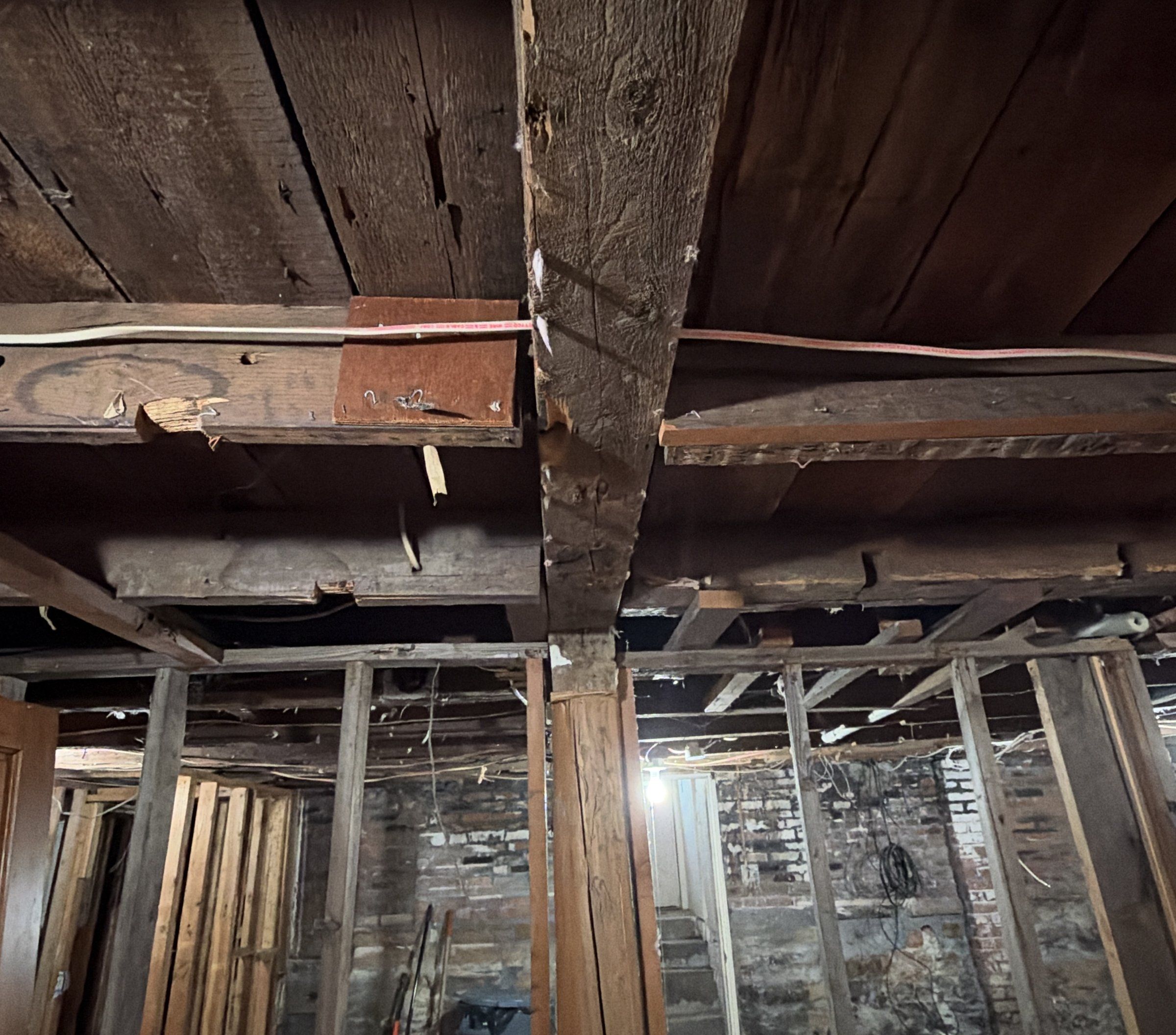
An 1800s three-family in Mystic, in Stonington. Permanent posts under every girder, hangers where the tenons pulled, room for the ridge post's footing.

Tidal Build brought me a 16-sheet permit set for a rear addition and renovation in Ledyard. The plan was a full-width single-story addition across the back of the house, and the part that needed engineering: about 44 ft of the first-floor rear bearing wall coming out, opening the back of the house into the new space.
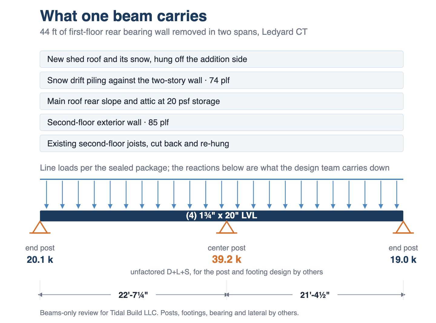
That wall was holding up more than most people would guess. The second-floor joists land on it. The second-floor exterior wall sits on top of it. Behind that wall the attic and the rear slope of the main roof both work their way down to the same line. And once the addition goes on, the new shed roof hangs off it too.
All of that had to end up on one beam.
The architect had already drawn a beam. That happens more than people expect with good design-build firms, and it is a reasonable place to start. What Tidal needed was somebody to check it against the real loads for that town, verify the other two beam lines, report the reactions, and put a stamp on it for the building department.
We scoped it as a beams-only review. Three beam lines, sized and verified, with the support reactions tabulated so the design team could carry them down. Posts, footings, bearing details, connections, lateral bracing and uplift hardware stayed with them, and the package states that in writing rather than leaving it to be assumed.
Scoping it that way is deliberate. A narrow scope that says exactly what it covers is more useful to a builder than a broad one that is vague at the edges.
The transfer beam came out as four plies of 1-3/4 by 20 in LVL over two spans, 22 ft 7 in and 21 ft 4 in, on a center post. Under dead, live and snow together the center post takes a little over 39,000 lb and each end post about 20,000 lb, and those reactions are what the design team sizes the posts and footings from.
Strength was never the hard part. What came closest to the limit was stiffness.
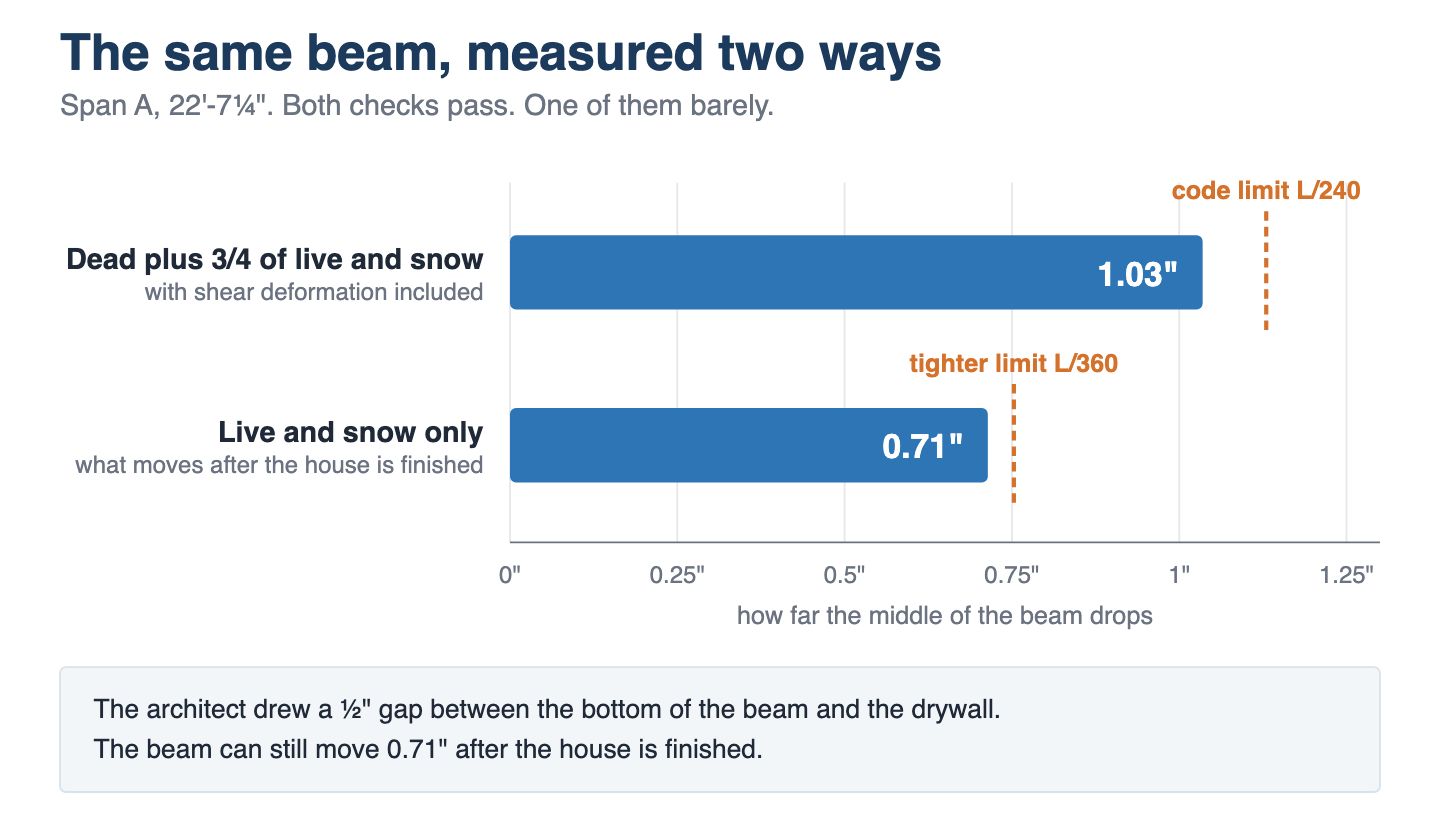
On a span this long, bending demand grows with the square of the length while sag grows with the fourth power. Past twenty feet or so that gap starts to matter, and deflection quietly takes over as the check that picks the member. On span A, dead load plus three quarters of the live and snow load, with shear deformation included, computes at L/262 against a limit of L/240. Live and snow on their own come to L/380 against L/360. Both pass. Neither passes by much.
I accepted it at the code limit rather than asking for a heavier member, and said so in the package: the total-load deflection is code-compliant and sits near the limit, and the half-inch gap the drawings already called for between the bottom of the beam and the drywall is the right detail for a beam of this span class. The drawings carried that gap before anyone asked for it, which is a good sign about a set.
Ledyard sits at 30 psf ground snow, and the Connecticut code puts the flat-roof design load on this addition at the same 30 psf.
The part that is easy to miss is what happens where the new low roof meets the two-story wall of the existing house. Snow blows over the top of the tall wall and drops into the corner behind it, so it does not sit evenly. It banks up. On this roof that drift added about 74 pounds per foot to the transfer beam.
Snow is heavy. Think about leaning a load of building material against the side of a house and asking whether the wall would care. Water and snow are the same kind of weight, and they show up every winter whether the drawing accounted for them or not.
The building official, reviewing the permit, asked for calculations on the 2 ft overhang wall that the drawings carry on 14 in I-joists. That was outside the beams-only scope, and it was a fair question. The joists were adequate as drawn, no cantilever reinforcement and no web stiffeners, with one framing item added: a doubled joist under each jamb of the 5 ft kitchen window. A short sealed letter went to the town through the architect.
Eight weeks after the package sealed, the contractor asked for a framing change. He wanted to delete the beam below the existing garage ridge, and its two posts, and have the new shed rafters stop on a plate laid on the existing garage roof instead, with the garage rear wall still the intermediate support. I asked for photographs of the garage attic before saying anything. They showed 2x4 metal-plate trusses, not rafters, which changes the question: a truss is a designed assembly, and I did not have its drawings and would not certify it.
The revision works around that. The rafters run from the eave, over the garage rear wall beam, and stop where the new 3:12 roof meets the garage roof, bearing on a doubled 2x6 plate screwed to each truss. On each truss a 2x8 scab runs on one face of the top chord from web joint to web joint in the panel the plate lands in, so the scab carries the plate load across the chord panel on its own. The part of the garage slope that ends up under the new roof carries no snow once the new roof is on, and at any meeting point from 4 to 10 ft out from the garage rear wall, that takes more load off each truss than the plate puts back on it. The garage rear wall beam picks up more load with the rafters bearing on it instead of hanging on the deleted beam, so its clear-opening limit in the wall below came down from 18 ft to 16 ft 6 in.
| Item | Detail |
|---|---|
| Building | Two-story single-family house with an attached garage, taking a full-width single-story rear addition |
| Framing | Wood-frame platform construction. New 2x12 shed rafters at 3:12 over the addition, existing second-floor joists cut back and re-hung on the new transfer beam. Existing garage roof on 2x4 metal-plate wood trusses |
| Foundation | Existing poured concrete at the house. The addition on a pier line a full story above grade |
| Existing condition | Reviewed from the architect's 16-sheet permit set, with existing conditions carried as stated assumptions and a conservative design envelope. No site visit |
| Scope | Independent review and stamped calculations for three new beam lines, beam sizing only, with the support reactions tabulated for the design team. Posts, footings, bearing details, connections, lateral bracing and uplift hardware stayed with the design team and are stated as excluded. A later revision deleted one beam line and put the new rafters on the existing garage trusses |
| Rear bearing wall removed | About 44 ft, in two spans |
| Transfer beam span A | 22 ft 7 1/4 in |
| Transfer beam span B | 21 ft 4 1/2 in |
| Center post reaction | 39.2 kip, unfactored dead plus live plus snow, simple spans |
| Transfer beam deflection, span A | L/262 on dead plus three quarters of live and snow, against L/240; L/380 on live and snow, against L/360 |
| Garage rear wall beam, clear opening limit | 16 ft 6 in after the revision (18 ft before it) |
| Transfer beam at the removed rear wall | (4) 1-3/4 in x 20 in LVL, 2.0E, two spans on a center post, posts by others |
| Garage rear wall beam | (3) 1-3/4 in x 14 in LVL, 2.0E, on a 2x6 cripple wall |
| Ridge-line beam at the garage | (3) 1-3/4 in x 14 in LVL, 2.0E, and its two PSL posts. Deleted in Revision 1 |
| Plate on the existing garage roof | (2) 2x6 laid flat and stacked on the sheathing along the meeting line, two 6 in structural screws into each truss, hurricane tie from each rafter |
| Scab on each garage truss | 2x8 on one face of the top chord in the panel the plate lands in, web joint to web joint, screwed to the chord, nothing driven through the truss plates |
| Shed rafters | 2x12 No. 2 Douglas Fir at 16 in o.c., one piece from the eave to the plate, seat cut on the beam not more than 1-1/2 in |
| Load path | The new shed roof hangs off the addition side of the transfer beam while the existing second-floor joists are cut back and re-hung on the house side. Above that the beam picks up the second-floor exterior wall, the attic at limited storage loading, and the rear-slope reaction of the main roof. All of it runs out to an end post at each end and one center PSL post, and down from there to the foundation |
| Loads carried | main roof rear slope, new shed roof, snow, including leeward drift against the two-story wall, attic at limited storage, second floor, second-floor exterior wall |
| Ground snow load | 30 PSF |
| Code basis | 2022 Connecticut State Building Code (2021 IRC and IBC basis), ASCE 7-16, NDS 2018 and published manufacturer LVL design values |
Tidal Build is a design-build firm out of Mystic with no engineer in house. That is a good fit for how I like to work: they draw it, they have real instincts about structure, and I do the math and take responsibility for it. The workflow is the same on every job we do together. Calculation package and comments from me, their drafter incorporates, I stamp the final revision.
A lot of towns want calculations signed by a professional engineer before they will issue a permit on an opening this size, and plenty of architects would rather hand the structural math to someone who does it every day. On this one the architect had already drawn a beam that worked. My job was to prove it, size it against the real loads for that town, and put a stamp on the arithmetic.
It sizes and verifies the beams, and it reports the reactions those beams deliver at each support so somebody else can design the posts and footings. It is not a review of the whole structure. On this project posts, footings, bearing details, connections, lateral bracing and uplift hardware were excluded, and the package says so in writing.
The stamped package stands for what it describes, so a change gets a revision, not a verbal okay. Here the contractor wanted to drop a beam and its two posts and land the rafters on the existing garage roof. I asked for photographs of the garage attic, found trusses instead of rafters, and wrote a two-page revision with a plate and scab detail laid out so that no truss carries more total load than it does today. The original package stays in force except as the revision states.
An 1800s three-family in Mystic, in Stonington. Permanent posts under every girder, hangers where the tenons pulled, room for the ridge post's footing.
Structural review and stamp of a builder's permit set for a rear hoistway addition on a 1951 cape, with the roof, posts, foundation pinning and retaining walls designed from drawings and photographs.
Call or text Travis at (860) 519-6009, or send the details below. Stamped letters follow within a few business days of the visit, and you always talk to the engineer who stamps it.
This page describes engineering performed for a specific structure, reviewed from drawings. Spans, member sizes, and connection details are particular to that building and its loading. Nothing here is a design for any other structure. Every project requires its own analysis by a licensed engineer.